The image processing functions in the CIIPS Glory soccer programs for year 1998 and 1999 uses lookup tables to determine distances. These lookup tables depends on the cameras physical position, the servo configuration on the hardware description table and the lens view angle. The tables assume a tilting camera.
The original programs ran on Eyebot robots with Color Quickcam, and the current tables reflect the settings which was valid then. The current robots have different HDT settings, some of them have different lenses and others use different cameras (EyeCam).
This document gives a short description on how to calibrate the tables. The method was developed by Birgit Graf for her diploma Thesis.
Before the camera can be used, we need to make sure the lens is in focus. Focusing is done by turning the lens in it's socket. The QuickCam lenses can be turned right away, while the EyeCam lenses need to have a screw on the side unscrewed before they will move.
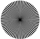
The simplest way to focus the cameras is to connect them to a PC to see the color images at full framerate. By using a simple pie drawing with 2.5 degree black and white arcs, focusing is done by turning the lense until the blurry center is as small as possible1. Figure 1 gives an example of this pattern.
The soccer code uses two lookup tables to calculate different distances and pixel widths. Each table has tree different settings, reflecting the tree camera angles used; middle=0, up=1 and down=2. The two tables are used for horizontal and vertical calculations.
The horizontal table yfact[3][imagerows] gives the multiplication factor for each row to convert pixels to meters. It can be used to convert m meters to p pixels on a given row. campos is the numeric representation of current camera position.
| (1) |
This is used to predict the ball width in pixels when searching for the ball in the images.
It can also be used to convert pixels to meters. This assumes that the camera is mounted in the center of the robot, and calculates pixels to the left or to the right of the robot axes. The field pixel located at (xpos,ypos) will then be located my meters to the left or right of the robot.
| (2) |
The yfact table is generated using a rectangular white or light sheet of paper, placed perpendicular to the view direction. The robot is placed on the soccer field, and the paper is placed in the upper center of the image. The camera servo must be set to the correct angle. Check servos.c for the correct values.
Make sure the paper is visible in the upper rows of the image, and that the edges are visible. Take a snapshot. Move the robot closer to the paper. The paper will now cover rows further down in the image. Take a new snapshot. Continue with this procedure until all rows are covered. You will need tree sets of snapshots, one for each camera servo setting. To take snapshots I used the ImACam eyebot program. This will produce PPM images and upload them to the PC.
Using these images, you then measure the pixel width of the piece of paper for each row in the image. This width, p, is then used together with the paper width, w, to calculate the yfact value, fy.
| (3) |
To measure the pixel width, I used xv to display the image, ' > ' to enlarge the image and the middle mouse button to read the pixel width.
To find the distance to the robot along the view direction, the soccer programs uses the table x2m[3][imagerows]. It translates from pixel row to distance in meters from the camera. To make this table, the distance to the edge of a sheet of paper is measured, together with the row number it appears in. This needs to be done for each row, and for each camera servo setting.
To find the distance mx from the robot, a simple table lookup is
performed:
| (4) |
When the measured values are collected, one can use various tools to find a formula which closely matches the measured values. I used Mathematica, with the help of Thomas Hanselmann, to interpolate one reading into a polynomial.
From the dataset, I made a textfile dataXY.txt with the coordinates (x,y) as s space separated list: ``x1 y1 x2 y2 ...''.
I then used the following Mathematica commands to make the formula. You might have to adjust the parameters to Fit to generate a more accurate formula.. The datafile must have all values on one line to make Mathematica happy.
dataXY = ReadList["data.txt",
  {Number, Number},
  RecordLists -> True][[1]];
func =  Fit[dataXY, {1, x, x^1.1}, x];
ymax = Max[Transpose[dataXY][[2]]];
pOriginal = ListPlot[dataXY,
  PlotJoined->True,
  PlotRange->{{0,61},{0,ymax}},
  PlotStyle->{Hue[0.1]}];
pFit = Plot[func, {x,0,61},
  PlotRange->{{0,61},{0,ymax}},
  PlotStyle->{Hue[0.6]} ];
Show[pFit,pOriginal]; func
The best way to do such camera calibration would be using a mathematical model for the camera, taking the known properties of the camera and the servo into account. If we make sure the HDT contains enough information to calibrate the cameras, the programs should be more generic and adapt better to changing settings. I hope to find time to investigate this further.
Complete Postscript file to make lens focus pattern.
%!PS-Adobe-1.0
%%Title: Camera lens focusing sheet
%%Creator: Petter Reinholdtsen <pere@td.org.uit.no>
%%CreationDate: 1999-12-04
%%BoundingBox: 13 14 574 575
%%Pages: 1
% Place this in front of the camera, and change
% focus until the black center spot is as small
% as possible.  The camera should then be in
% focus.
/cm { 28 mul } def .00001 setlinewidth
% Center of circle
10.5 cm 10.5 cm translate
% scale 1 to fill page
10 cm 10 cm scale
newpath 0 0 1 0 360 arc stroke
72 { newpath 0 0 moveto
  0 0 1 0 2.5 arc closepath fill 5 rotate
} repeat showpage
1Thanks to Mark Gaynor for this method.