
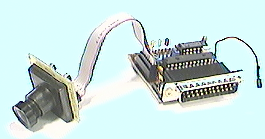
The Eyebot is a Motorola 68332 based robot controller with on-board camera support and various input and output connections available. Initially it used grey scale and color QuickCams. When Connectix introduced QuickCam VC without releasing the protocol specification and hence made it impossible to write drivers, an alternative was needed.
The solution was designing the EyeCam, specially made for the Eyebot and giving much better image quality. The problem was that the frame rate dropped to 3.7 frames per second. The reason for this is that the EyeCam lacks flow control, and the CPU must synchronize with the camera to read the data. This results in approximately 20.000 interrupts for every frame, one for every byte transfered from the camera. The EyeCam is capable of running at 60 frames per second, but this speed was to fast for the CPU. Processing one interrupt takes to long, and the data presented by the camera is no longer there when the CPU tries to read.
Several solutions to this problem was suggested, among these where connecting the camera directly to the memory bus, dual ported memory and adding flow control using a digital fifo. This paper describes the last solution.
The EyeCam is made from the VISION VV6300 CMOS Image sensor [VV6300] and a small support circuit to connect it to the parallel port (parport). The camera sensor is no longer produced and will be replaced with VV6301. The two sensors are supposed to be compatible. As we don't have a VV6301 sensor yet, all our tests are done with the older VV6300.
Configuration is done using serial communication on pin scl and sda. Frame start is signaled on the falling edge of pin fst and every byte is signaled ready on the falling edge of pin qck. The frequency of qck is specified using a clock divider, and the camera is capable of up to 60 frames per second.
The camera frame rate is controlled using a clock divisor given as 2n. This clock divisor sets the pixel frequency as shown in table 1. With our camera setup, the qck signal will qualify data on the falling edge with this frequency. If we assume equal spacing between rising and falling edge, the period t between falling and rising edge on qck can be found from the frequency f\sc qck in Hz: t = [1/(2f\sc qck)]. We verified the assumption by checking the qck signal with an oscilloscope.
The number of CPU cycles c available to read out the data before they disappear is then easily calculated using this period t and the CPU frequency f\sc cpu in Hz: c = t × f\sc cpu
| Clock Divisor | 20 | 21 | 22 | 23 |
| Data rate (kHz) | 895 | 448 | 224 | 112 |
| Frame rate (fps) | 29.99 | 15.01 | 7.5 | 3.75 |
| Data present t (ns) | 559 | 1120 | 2230 | 4460 |
| Cycles data present c | 19 | 39 | 78 | 156 |
| Cycles per pixel | 230 | 459 | 918 | 1861 |
Table 1 show the results for the possible clock divisors, assuming CPU running at 35 MHz. When we know that the CPU32 platform uses up to 92 cycles to enter and 24 cycles to exit the interrupt handler [CPU32], and the original optimized EyeCam driver [EyeCam] uses 78 cycles to process one byte, it is quite impressive that the original EyeCam driver is working. It is also obvious that there is no way to increase the frame rate above 3.7 with the current driver design.
The camera supports two image formats (160 ×120 and 164×124), different transfer modes and 4 and 8 bit pixel sampling. Each color pixel is the result of combining four camera pixels, one red, two green and one blue byte. One image is thus approximately 20 kB.
qck and fst can be configured in different modes to change which edge qualifies the data, and whether control information should be qualified as well. The image byte size (as qualified by qck) will change when the mode changes. We found the image size to be 20336 bytes when only image data is qualified and 22352 bytes when both control and image data are qualified.
We run the camera in max resolution and 8 bit pixel sampling. The frame rate can be doubled by using 4 bit pixel sampling, but when we tried to use this mode at 3.7 frames per second, the pixel noise made the images useless. We do not know why and have not yet tried using the 4 bit mode at other frame rates.
The limited processing speed of the current Eyebot platform is a real challenge. Still assuming 35 MHz CPU speed, and image size at 82×62 pixels, the number of cycles available to process one pixel at r frames per second is given by the following formula: n = [(f\sc cpu)/82 ×62 ×r]. The inspiring result is available in table 1. When we know that CPU32 instructions uses approximately 10 cycles to complete on the average, real time image processing with even 1861 cycles seems a bit hard.
| Camera pin | scl(1) | sda(14) | sin(11) | fst(12) | qck(10) |
| Parport pin | strobe(1) | slctin(17) | init(16) | busy(11) | ack(10) |
The camera control pins are connected to the parport as described in table 2. The parport is set up to generate interrupts and qck is connected to ack to trigger the interrupt when data is ready.
While working with the fifo, we discovered a design flaw in the EyeCam. The PC parport interrupt is triggering on the rising edge (0V�5V) of ack, while the camera qualifies data on the falling edge (5V�0V) of qck. We are not quite sure why the camera could work anyway, and intend to do some testing as soon as we find time. The easiest way to test this would be to swap fst and qck, and run the camera in a different mode where fst is the inverted qck. We have not investigated this any further
The basic idea of the fifo buffer is to add flow control to the data stream coming from the camera. The camera write data into the fifo at it's configured pace, and the CPU reads them out again when it has time, and as fast as it can.
Digital fifos are available with different capacities and with different speed requirements. We only needed to store 8 bits. The fifo access time was around 20-50 ns, with the faster fifos being a lot more expensive than their slower alternatives. Our access time requirements, as given in table 1, would be in the range 500 to 4500 ns. We did not find any 8 bit fifos, and settled on a 9 ×1024 bit 55 ns access time fifo in the IC 7200 family for our initial testings. It was cheap and easily available over the counter from Radio Spares.

The fifo has five control lines going in; read, write, reset, retransmit and expand. All of these are active low. When running the fifo in single mode, we do not use retransmit ( rt) and expand (XI), and these are connected to 5V and 0V respectively. The first documentation we got was a bit confusing on this subject, but after some testing we found this to work.
The fifo needs to be reset before it is used, and one must make sure the read and write signals are high when reset is taken low. Not doing proper reset give unpredictable results and gave us a lot of problems in the beginning. The fifo has tree control lines going out; empty, half-full and full. On the falling edge of the half-full line, the fifo is half full and we can start reading. When the full line goes low then the fifo is throwing away all the new data.
The first design decision was how to connect the fifo. We decided to continue using the parport, to make it easier to test the new buffer. This would make it possible to plug it in between the current EyeCam and the parport. The next question was how to connect the fifo to the parport and the camera.
The camera side was fairly straight forward. The camera data clock ( qck) needed to connect to the fifo write pin. We needed to make sure they worked with the same edge, and the documentation (and the oscilloscope) told us that this was the case. The data signals where connected to fifo data pin 0-7 and the configuration serial lines where connected directly to the parport as before. We did not quite know how to connect the camera frame start ( fst) signal, and tried various solutions. More on these later.
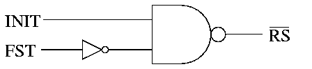
Reading the parport specification [ST16C552], we choose to connect the fifo control lines reset ( rs), read ( r), empty ( ef), half-full ( hf) and full ( ff) as shown on figure 2. We decided to connect camera frame start ( fst) to D8 and passing it though the fifo to parport busy much later.
Our first idea for fst was to connect it as shown on figure 3. This way the fifo would only be reset between frames if the parport init was low. This would also make sure the fifo always started reading from the camera on frame start. The only problem with using this approach would add one extra chip to the buffer board, making the buffer bigger and a bit more expensive, so the choice was easy when we found a way to do without this chip.
We tried connecting the fst directly to the parport busy, but was unable to find the proper frame start using this approach. We finally decided to connect the fst to the extra data pin and change the camera mode to toggle qck (and therefore write) during both control and image data. We later discovered that checking the busy line during read was to slow for our purposes and choose a software only approach for frame synchronization.
During our initial testing we used a hand-soldered test board with a 1k fifo. The initial testing went OK, but the board was fragile and we often needed to re-solder broken wires. Later when we had refined the design a bit, we ran into large problems getting the fifo to work properly. We believed this to come from long cables and problems with fifo reset, and where close to giving up when we decided to test with another fifo - this time a 2k fifo. This time the board started working again, and we concluded that the original fifo was fried.
After testing the control lines and struggling with interrupts for a while, we concluded that the current design should work and got our local electronic workshop to make a proper fifo test board. The only hardware design-question left was where to place the connectors. The obvious two options where discussed; placing it on the camera and placing it on the parport. We ended up placing it on the parport to avoid adding more weight to the camera. The camera connector is as close to the center of the robot as possible to make sure the cable would be as short as possible.
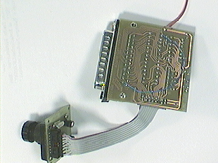
With a proper test board available, things worked even better. At this stage we where not sure which edge would trigger the parport interrupt so we included a jumper to switch from inverted and non-inverted half-full flag. We later found out that the PC parport trigger on the rising edge of ack, and ended up connecting the inverted hf to ack. The response time of the inverter can be ignored, as the half-full flag is set only around 20 times per frame.
We tried to use the camera chip ( ce) enable pin to stop the camera from transmitting data to the fifo when the full flag came up, but this did not work. When we connected ff to ce, only black images would come out of the camera. We tried contacting VLSI Vision Ltd (which was acquired by STMicroelectronics in early 1999), to ask about more details on this sparsely documented part of the camera. We got one reply with valuable information, but was also informed that
``STMicroelectronics operates a policy of offering direct support to high volume customers only. Support to low volume customers like yourselves is generally supplied by local distributors.''
and were thus unable to investigate any further. Our local distributor could not help us at all.
The buffer still did not work properly. After a few seconds the images would turn black, white or with a dithered pattern. When checking in the oscilloscope, it seemed like the data did not make it past the fifo. The control signals worked OK, the half-full flag would signal the driver as expected, but the data was missing. Looking at the autofdxt read pin, we suspected a problem with the shape of the read signal. When running at full speed, the signal would be too short and not very square, see figure 5.

We tried a few things to make the read signal better, but neither pull-up resistors nor buffers would make it any better.
During this process we discovered another hardware bug. The Eyebot MK 3 has pull-up resistors on the open drain parport UART control lines. It also has a pull-up resistor on parport data pin 2, as a user discovered and reported. While we were checking this bug, we found that this pull-up was supposed to connect to slctin, and by accident also discovered that the UART has internal pull-up resistors on all the open drain lines. We removed both the bogus and the duplicate pull-up resistors. This did not fix the problem with the read signal.
As we knew we where pushing the limit for the parallel port, we decided to try connecting the read line to one of the Eyebots digital output lines. This would give us a proper square read signal and the fifo would keep working. The only problem with this approach was that the digital output lines where already used for controlling the wheel motors, and keeping both the camera driver and the motor drivers off each others feet would be to slow.
Our next try was using one of the Eyebots TPU lines to drive the read pin. These proved to be to slow. We could not get them to read out from the fifo any faster than approximately 200 kHz.
When deciding how much data to store in the fifo, one needed to think of a few things. The most important consideration is how much time is needed for the CPU to start reading from the fifo. This must be less then the time it takes to fill up the second half the fifo. This time depends on the interrupt activation time, the fifo size S\sc fifo and the camera write speed f\sc qck and should be as high as possible.
The next thing to consider is how much latency the fifo adds to the images. When the complete image has been written to the fifo, it will only be available in memory after it is read out. This depends on the interrupt activation time and CPU readout speed, and should be as low as possible.
To make sure the camera interrupt does not interfere with the other system interrupts, one call to the interrupt handler should be as short as possible, yet each call should do enough work to reduce the overhead per byte transfered.
One must make sure the fifo half-full flag is set when one image is complete. When the frame size Sframe isn't a multiple of half the fifo size, the simplest way to fix this is to read out the image size modulo half the fifo size when starting to read one frame. This will make sure the last half-full flag is set when the last byte of the image is written to the fifo. The number of fifo readouts and thus the number of interrupts will be �[(2 Sframe)/(S\sc fifo)] �.
We choose to implement the fifo driver with the same API as the current RoBIOS camera functions [RoBIOS]. The API consists of CAMInit() to set up the camera plus CAMGetImage() and CAMGetColImage() to get a 4 bit grey scale or 24 bit color image from the camera.
The camera original driver consists of two separate layers, one layer is the interrupt handler fetching bytes into one ``raw'' buffer, and one layer to process the ``raw'' bytes into the expected image format.
While writing the driver, we ran into a few problems. The most annoying was trying to get information out of confusing and incorrect documentation [ST16C552]. It was hard to find out which control lines where active low, and we ended up testing every pin. The fifo outline summarized our findings, with a line about the pins that are active low.
The first prototype driver did not use interrupts, but would only reset the fifo and wait for the half-full flag to come up before reading out as fast as possible. This first naive C version was able to read at approximately 250 kHz, and we later managed to optimize the C code to read at approximately 330 kHz. This driver would constantly loose frame synchronization, as the fifo went full between the reading periods when the images where processed and displayed. To solve this problem we needed to get the interrupt triggering going.
It was very hard to get the half-full flag to trigger the interrupt. The first problem was finding the correct edge which triggered the interrupt. When this was finally solved by adding an inverter between hf and ack, we discovered a new problem. Even if the interrupts where configured and enabled, the driver would only sometimes start as it should. It was as if the first half-full signal was ignored, and the driver would block forever as the fifo already was full and no new interrupt would be triggered.
The only solution to this problem was to add timeouts to the code and stop the camera and reset the fifo when a timeout occurred. With this in place, the interrupts would work as expected after only a few resets.
When we got the interrupt handling working, we discovered that serial communication no longer worked. If we stopped the camera interrupt, everything worked as normal. The current RoBIOS 3.1 API does not have a function to signal that the camera is no longer needed. We suggest adding a function CAMRelease() to make it possible to stop the camera to save battery and stop wasting CPU-cycles processing interrupts when no one will be using the images. This would also make it possible to ``enable'' serial communication.
To let the camera driver handle any fifo size, and automatically detect the presence of a fifo, we came up with the following procedure. We configure and start the camera and let it fill up the fifo (with a timeout until the full flag is set). Then we stop the camera and start reading out the data until the empty flag is set. The number of bytes read should then be the size of the fifo. If this procedure fails, timing out while filling up the fifo, or being unable to empty the fifo, the camera is stopped and we assume there is no fifo present.
With the current API, the image data needs to be stored in a image buffer before it is copied into the user supplied image buffer. The current camera API also requires the image bytes to be shuffled to match the 24 bit image format. To save processing time, and avoid copying data, we suggest changing the API to let the user supply ``raw'' image buffers which are returned when the image bytes are fetched from the camera. Then it will be up to the programmer if he wants to use the ``raw'' camera data or transform it into the standard 24 bit image format. We therefore propose the following addition to the RoBIOS camera API:
Get the size of the raw camera frames. This size would be different for different camera types.
Give one memory block to the camera driver. The memory block must have at least the size of the returned value from CAMRawFrameSize().
Return true (1) if one complete image is available, and false (0) if no image is ready.
Get one camera frame from the camera driver. Block if no camera frame is available yet, but there are buffers available to fill. Return NULL if there are no more raw camera frames available to fill.
Convert one raw camera frame to the standard 24 bit image format.
Stop the camera and disable parport interrupt.
  int buffersize = CAMRawFrameSize();
  BYTE *buffer1 = malloc(buffersize);
  BYTE *buffer2 = malloc(buffersize);
  /* Initialize camera and prepare double buffering */
  CAMInit(NORMAL);
  CAMPutBuffer(buffer1);
  CAMPutBuffer(buffer2);
  while (1) {
    if (CAMBufferReady()) {
      BYTE *rawframe = CAMGetBuffer();
      /* process raw frame */
      CAMPutBuffer(rawframe);
    }
  }
  CAMRelease()
  free(buffer1);
  free(buffer2);
Adding a simple fifo between the EyeCam and the Eyebot improved the frame rate and brought us closer to the fundamental limitations of the platform. Adding flow control to the camera made it possible to fetch images faster then it is possible to intelligently process them on a 35 MHz CPU.
It would be possible to increase the frame rate even further by connecting the fifo directly to the CPU bus in such a way that every read from the fifo automatically strobed the read pin. This way the readout speed would be limited by the speed of one instruction, instead of the current approach where the read pin must be manually toggled.
One way to do this is to connect the parport chip select ( csp) and one extra address line to the read pin in such a way that the read pin goes low every time the mirrored parport data address is read. This requires memory mirroring to work. We have not investigated this, as it requires hardware modifications to the Eyebot controller. Another approach would be to bypass the parport completely, making sure the fifo presents data on the low 8 bits on the data bus.
It might be possible to speed up fifo reset by connecting the inverted fifo reset line to the camera soft reset (SIN) pin. This way the camera and the fifo would be reset using one pin, and without the need to stop the camera. This requires that setting the SIN high also sets qck high.
Decreasing the image resolution will give more time to process each pixel, and there are a few simple approaches. By changing the camera mode to use ``slow qck'', only every second byte would be written to the fifo, and the resolution would be reduced to 40×60 pixels. This might buy us some extra processing power.
We do however believe the only solution would be to upgrade the CPU to a faster and more powerful one is the only solution to be able to do real time image processing on the Eyebot. A few alternatives are available, and we suggest checking out the StrongARM ST-1100 [StrongARM] closely.
Thanks to Thomas Br�unl, Director of the Mobile Robots Lab and creator of the EyeBot robot family, for giving us the possibility to play with the robots in the first place. Thanks to Klaus Schmitt for all his help with the parport interrupt handling. Thanks to Ivan Naubronner for giving all his help on the electronic design.
Thanks to Ken Cormack at STMicroelectronics for valuable information on the VV6300 sensor, despite the company policy to not help the low volume costumers.
Petter Reinholdtsen can be reached via email to pere@td.org.uit.no. Stephen T. Humble can be reached via email to steve@newton.dialix.com.au.
Information on the EyeCam and the Eyebot is available from
http://www.ee.uwa.edu.au/~braunl/eyebot/.
This article was rejected when submitted for RoboCup 200 workshop. Here is the rejection letter. I was initially planning to update the paper based on the comments, but later discovered I would never take the time required to do it.
From: Gerhard Kraetschmar <gkk@acm.org>
Date: Thu, 22 Jun 2000 23:33:16 +0200
Message-Id: <3952861C.22CE96DD@acm.org>
To: pere@hungry.com
Subject: Notification of Workshop RoboCup-2000 submission

Dear author,

we regret to inform your paper has not been accepted for presentation
at the RoboCup-2000 Workshop.

Because the number of submissions to this workshop has grown
in recent years, we have had to decline many papers that would have been
accepted previously.
We had a large number of high quality submissions and an acceptance
rate of about 30% for oral presentation.

Reviews of your articles are attached below.

We look forward to a very exciting and successful workshop and
sincerely hope that you will be able to attend.

Best regards,
        Peter, Tucker, and Gerhard

==============================================================
RoboCup 2000 Paper Review Form

Code: RK-9
Title: Speeding up a digital camera
Authors:  Reinholdtsen, Humble

COMMENTS FOR AUTHORS
Recommendation:
     ___ Accept  ___ Marginal accept ___ Marginal reject      X    Reject

Confidence in your recommendation:
    X     High     ___ Medium       ___ Low

Is the paper a good fit to the symposium?
     ___ Yes      ___ Somewhat     X  No     ___ Unsure

Is the work sufficiently novel to warrant publication?
     ___ Yes      X Somewhat     ___ No     ___ Unsure

Does it provide a reasonable amount of detail for a workshop paper?
     ___ Yes      X  Somewhat     ___ No     ___ Unsure

Are the implementation and experimentation sufficient? (if
applicable)  Keep in mind that the paper may describe work in
progress.
     ___ Yes      X  Somewhat     ___ No     ___ Unsure

Are the technical sections well-formed and accurate?
     ___ Yes      X Somewhat     ___ No     ___ Unsure

Is the presentation well organized?
     ___ Yes      ___ Somewhat     X  No     ___ Unsure

Is the literature survey adequate for a conference paper?
     ___ Yes      ___ Somewhat     X  No     ___ Unsure

What did you like best about this paper?
It  may  be an  interesting  paper  about  designing digital  cameras,
provided the  paper is cleaned up  by removing all  "fairy tale" style
and narration about partial failures  (which may be good in a tutorial
paper, but not in a scientific one).
However, the  only reference to the  RoboCup is the  picture in fig.1,
whose quality is quite questionable anyway.

When revising this paper, what do you think the author(s) should give
highest priority to?
If the  paper is  accepted, it should  definitely point out  much more
clearly what contribution  this work may provide to  RoboCup teams and
RoboCup-related research.
English should also be revised.

Other comments for authors (elaborate on any negative rankings above):
The  paper is  of very  marginal  interest to  the RoboCup  community,
unless some  specific experimentation is  carried out. But  that would
mean re-writing  almost the whole  paper. In this format,  the RoboCup
workshop audience is not the right target for this paper.

==============================================================

==============================================================
RoboCup 2000 Paper Review Form

Please return your reviews by June 5th, 2000 to gkk@acm.org

Code: RK-9
Title: Speeding up a digital camera
Authors:  Reinholdsten, Humble


COMMENTS FOR AUTHORS


Recommendation:
     ___ Accept   ___ Marginal accept ___ Marginal reject  x___ Reject

Confidence in your recommendation:
     x___ High     ___ Medium       ___ Low

Is the paper a good fit to the symposium?
     ___ Yes      ___ Somewhat    x ___ No     ___ Unsure

Is the work sufficiently novel to warrant publication?
     ___ Yes      ___ Somewhat     x___ No     ___ Unsure

Does it provide a reasonable amount of detail for a workshop paper?
     x___ Yes      ___ Somewhat     ___ No     ___ Unsure

Are the implementation and experimentation sufficient? (if
applicable)  Keep in mind that the paper may describe work in
progress.
     ___ Yes      x___ Somewhat     ___ No     ___ Unsure

Are the technical sections well-formed and accurate?
     ___ Yes      x___ Somewhat     ___ No     ___ Unsure

Is the presentation well organized?
     ___ Yes      x___ Somewhat     ___ No     ___ Unsure

Is the literature survey adequate for a conference paper?
     ___ Yes      x___ Somewhat     ___ No     ___ Unsure

What did you like best about this paper?

I'm a hardware hobbyist, so I like the work that was done to interface
a digital camera to a simple microprocessor.  But using a FIFO to
accomodate peripherals with that are asynchronous to the system bus is
a very standard idea.  It is also not appropriate for this workshop.


When revising this paper, what do you think the author(s) should give
highest priority to?


Other comments for authors (elaborate on any negative rankings above):

I like the work, but it would be better suited to a hardware
conference specifically devoted to microprocessor issues.  If you're
looking for a better image processor, you might try DSP chips like the
Analog Devices ADSP2181, which have direct DMA from external devices
into internal memory, and much more processing power.
==============================================================