During the fall of 1999, the CIIPS Glory robot soccer team started to look into how to connect a compass to the Eyebot controller. Initially, we used dead reckoning to keep track of the heading. This method obviously do not work when the robot is pushed a little of track, and is also accumulating error when the wheels slip. To compensate for these problems and improve our results, we decided to have a look at electronic compasses.
We first learned about one digital compass, the ``Vector 2X'' from Precision Navigation, Inc. The ``Vector 2x'' is circa 3.8 ×3.3×1 cm. This document gives a summary on how this driver works, and how to connect and set up such compass with the Eyebot.
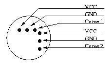
We later learned about the ``Analog sensor no. 1655'' from Dinsmore Instrument Company, a analog compass delivering two output indicating the heading of the compass. The ``Analog sensor no. 1655'' is circa 1.3 cm in diameter and circa 1.6 cm tall. This document describe how to connect and read out the heading from this compass.
The digital compass is supposed to have accuracy of 2°. We have not tested or verified this at the moment. We are running the compass with maximum resolution and in master mode to get the heading of the compass. With maximum resolution it gives an updated heading 2.5 times a second.
This compass could be used with or without an inverter. Without inverters, the compass must be reset in soft software.
With inverters, DOUT 1 and 2 should be inverted, and RESET should be not connected.
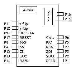
The digital compass get power (VCC) and ground (GND) from the Eyebot PSD connector. It needs 5 ±0.25 Volt. The control signals to the compass are connected to the Eyebot digital output connector (DOUT). The control signals from the compass is connected to the servo connector S12 (TPU 13) and the PSD connector. The compass connector names and layout is shown in fig 1.
The wires should then connect as given in this table, with the different connectors and connetor pin number given for the Eyebot side.
To make it possible to mount the compass upside down, the X and Y flip pins should be connected to ground using a strap, to make it configurable which way the compass should work.
| Vector2x | Eyebot |
| P1 (SCLK) | SERVO 1 (TPU) |
| P16 (GND) | PSD 1 (GND) |
| P15 (VCC) | PSD 3 (VCC) |
| P2 (SDO) | PSD 4 (DIN) |
| P5 (P/C) | DOUT 1 (DO5) |
| P6 (CAL) | DOUT 2 (DO6) |
| P17 (RESET) | DOUT 3 (DO7) |
| P10 (Y FLIP) | GND or N/C |
| P11 (X FLIP) | GND or N/C |
| P3 (SDI) | N/C |
| P4 (SS) | N/C |
| P7 (RES) | N/C |
| P8 (M/S) | (GND) |
| P9 (BCD) | N/C |
| P12 (CI) | N/C |
| P13 (EOC) | N/C |
| P14 (RAW) | N/C |
The compass driver is included in a modified version of RoBIOS 3.1. The compass is set up using a hardware description table (HDT) entry like this:
compass_type compass =
  {0, /* version */
  13, /* TPU channel - SCLK */
  (void*)OutBase, 5,  /* P/C */
  (void*)OutBase, 6,  /* CAL */
  (void*)InBase,  5}; /* SDO */

HDT_entry_type HDT[] =
{
  ...
  {COMPASS,COMPASS,"COMPAS",(void *)&compass},
  ...
};
The RoBIOS driver uses one Time Processor Unit (TPU) channel to generate an interrupt on the rising edge of the SCLK signal. The interrupt handler then reads out the current value of the SDO signal on the digial input line given in the hardware description table.
When the compass is connected without an inverter, the RoBIOS kernel must be compiled with USE_COMPASS_NO_INVERTER defined to use it properly.
- Temperature control when soldering (documentation warning)
| VCC | AIN 1 |
| GND | AIN 9 |
| Curve 1 | AIN 3 (CH2) |
| VCC | AIN 2 |
| GND | AIN 10 |
| Curve 2 | AIN 4 (CH3) |
- XXX describe generic API
int COMPASSInit (DeviceSemantics semantics);
int COMPASSCalibrate (int mode);
int COMPASSStart (BOOL cycle);
int COMPASSCheck (void);
int COMPASSGet (void);
int COMPASSStop (void);
int COMPASSRelease (void);
http://dinsmoregroup.com/dico/
http://www.precisionnav.com/